- GD&T
GENERAL DIMENSIONING- International Paper Size Standards
- Technical Drawing Styles
- ISO And ANSI Projections
- ANSI Technical Drawing Views
- Technical Drawing Dimesioning Types
- ANSI and ISO Geometric Tolerancing Symbols
- Geometric Tolerancing Reading
- Taylor Principle Rule#1
- Form Tolerances
- Profile Tolerances
- Orientation Tolerances
- Location Tolerances
- Runout Tolerances
- TOLERANCES
ANSI AND ISO- Tolerancing and Engineering Standards
- Hole and Shaft Basis Limits And Fits
- ISO International System For Limits And Fits
- International Tolerance Grade (IT)
- Fundamental Deviations For Hole and Shaft Basis
- ISO Tolerance Band IT01-IT16
- Calculation Of International Tolerance
- Calculation of Upper and Lower Deviation For Shaft
- Calculation of Upper and Lower Deviation For Holes
- ISO Shaft Tolerances (3mm-400mm)
- ISO Shaft Tolerances (400mm-3150mm)
- ISO Hole Tolerances (3mm-400mm)
- ISO Hole Tolerances (400mm-3150mm)
- ANSI Standard Limits and Fits
- METAL CUTTING TECHNOLOGIES
- Terms and Definitions of the Cutting Tools
- Cutting Tool Materials
- Selection of Carbide to machine the work-part
- Identification System For Indexable Inserts
- Work-Part Materials
- Machinability and the specific cutting force
- Machinability of the Certain Material Evaluations
- Cutting Forces and Chip Formations
Cutting Forces and Chip Formations
A force that is generated by the cutting tool as it machines the work-piece. The cutting process assumed that the chip is removed from the work-piece by a shearing action across the plane. Because the deformed chip is in compression against the face of the tool a frictional force is developed. The work of making the chip must overcome both the shearing force and the frictional force. Cutting Force "Fc" acting in the direction of cutting Thrust Force " Ft "needed to keep the tool in the work-piece which direction perpendicular to the work-piece surface. At high positive rake angles the thrust force is negative and the tool is pulled into the work-piece. The forces on a cutting tool for a given material depend on a number of considerations; Cutting force increases with chip size. Thrust force is decreased if the cutting tool nose radius is made larger or if the side cutting edge angle is increased. Cutting force is reduced 1% as back rake angle is increased one degree. Tool forces are not changed significantly by a change in cutting speed. The greater the feed of the tool, the larger the forces. The greater the depth of cut, the larger the forces. Using a coolant reduces the forces on a tool slightly but greatly increases tool life. When removing material starts over the work-piece, some deformation zone will exist between cutting tool and on the work-piece. These steps are would be following one another such as primary deformation zone – shear in the work material, secondary deformation zone – friction between chip and rake face, tertiary deformation zone – friction between machined surface and flank face.
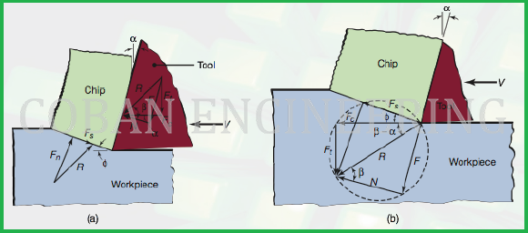
a-) Forces is acting on a cutting tool in two-dimensional cutting. Note that the resultant forces,
R, must be collinear to balance the forces.
b-) Force is circle to determine various forces acting in the cutting zone.
Fc = cutting measured by dynamometer
Ft = thrust force measured by a dynamometer
Fs = Shear force. The force that causes shear deformation to occur in the shear plane
F= frictional force
Fn= Force normal to the Shear force; the resistance offered by the work-piece
N = Normal force to the friction acting on the chip by the cutting tool on the cutting rake face.
R =Resultant forces
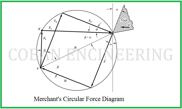
Forces in Metal Cutting Resultant Forces;
Forces in Metal Cutting Resultant Forces;
Vector addition of F and N = resultant R
Vector addition of Fs and Fn = resultant R'
Forces acting on the chip must be in balance;
R' must be equal in magnitude to R
R' must be opposite in direction to R
R' must be collinear with R
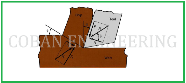
To show Active Forces on Chip:
Forces acting in metal cutting on the chip in orthogonal cutting;
Friction force F and Normal force to friction N
Shear force Fs and Normal force to shear Fn
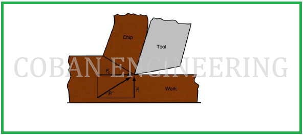
Relationship between Cutting Force and Thrust Force:
Forces acting in metal cutting on the tool that can be measured.
F, N, Fs, and Fn cannot be directly measured
Forces acting on the tool that can be measured:
Cutting force Fc and Thrust force Ft
Copyright ©2010-2023 Coban Engineering.All Rights Reserved.


