- GD&T
GENERAL DIMENSIONING- International Paper Size Standards
- Technical Drawing Styles
- ISO And ANSI Projections
- ANSI Technical Drawing Views
- Technical Drawing Dimesioning Types
- ANSI and ISO Geometric Tolerancing Symbols
- Geometric Tolerancing Reading
- Taylor Principle Rule#1
- Form Tolerances
- Profile Tolerances
- Orientation Tolerances
- Location Tolerances
- Runout Tolerances
- TOLERANCES
ANSI AND ISO- Tolerancing and Engineering Standards
- Hole and Shaft Basis Limits And Fits
- ISO International System For Limits And Fits
- International Tolerance Grade (IT)
- Fundamental Deviations For Hole and Shaft Basis
- ISO Tolerance Band IT01-IT16
- Calculation Of International Tolerance
- Calculation of Upper and Lower Deviation For Shaft
- Calculation of Upper and Lower Deviation For Holes
- ISO Shaft Tolerances (3mm-400mm)
- ISO Shaft Tolerances (400mm-3150mm)
- ISO Hole Tolerances (3mm-400mm)
- ISO Hole Tolerances (400mm-3150mm)
- ANSI Standard Limits and Fits
- METAL CUTTING TECHNOLOGIES
- Terms and Definitions of the Cutting Tools
- Cutting Tool Materials
- Selection of Carbide to machine the work-part
- Identification System For Indexable Inserts
- Work-Part Materials
- Machinability and the specific cutting force
- Machinability of the Certain Material Evaluations
- Cutting Forces and Chip Formations
Taylor Principle Rule#1 (Envelope Principle)
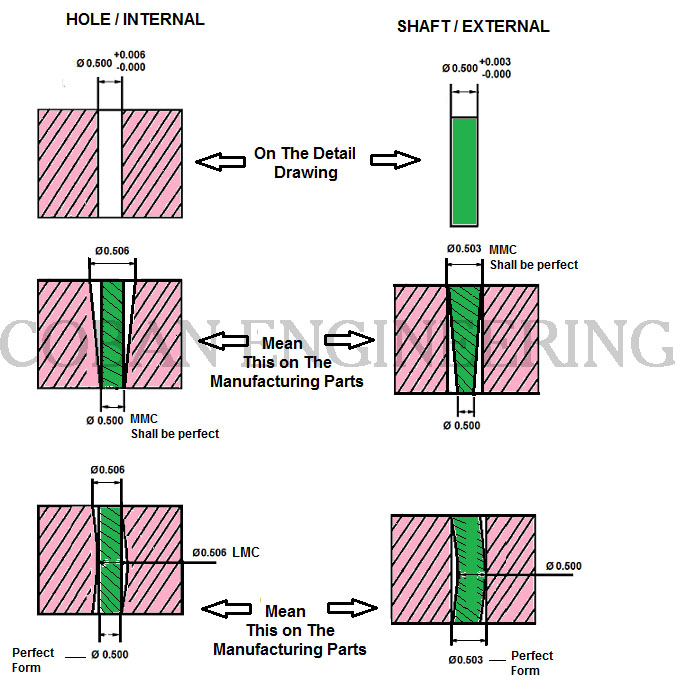
Taylor Principle is defined by rule #1 in geometric dimensioning and tolerancing within ASME Y14.5M - 1994. It is also known as Envelope Principle. This Principle (Rule#1) is based on the premise that a shaft must be able to fit inside a hole which is as deep as the shaft length. In this case the shaft is perfectly cylinder and the shaft in its largest size (MMC).In addition; A bore must be able to receive a shaft which is as long as the hole depth. In this case the hole is perfectly cylinder and the hole in its smallest size (LMC). In this principle, invented Go Gauges by Taylor in use to check and verify violations and conformance of the MMC. These are more commonly known MMC of the size feature. The intent of the Rule#1 is control the form of a size limits feature. Iso does not recognize rule#1. When the size of the limits is specified for the individual feature of the size, the form of this feature shall not extend beyond an envelope (boundary) of perfect form at MMC. The size of the part at MMC, the feature of the form has to be perfectly straight. If the actual part size smaller than the MMC, the allowed form variation is equal to the difference between actual part size and MMC. By the Rule#1 external or internal parts can be inspected by GO Gauges. Go Gauges is requirement for this principle. See figure below,

GEOMETRIC TOLERANCING UNDERSTANDING
FORM TOLERANCES
Form tolerances can be state by four tolerance zone. These form tolerances are Straightness, Flatness, Circularity, and Cylindricity. These form tolerance apply to individual features therefore the Form Tolerances are not related to datums.
Straightness:
Straightness is a two-dimensional geometric tolerance. Straightness is a condition where one line element of a surface or an axis must lie in a straight line. It controls how much a feature of one line element of a surface can deviate from a straight line. Straightness tolerance is applied in the view where the elements to be controlled. Straightness tolerance specifies a tolerance zone within element or derived median line must lie. The feature control frame needs to be attached to the surface with an extension line or a leader when a surface needs to be controlled. Tolerance zone for both cylindrical and flat surface is applied along the entire surface.

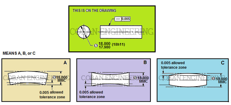
On the figure shown above, Each longitudinal element of the surface must lie between two parallel lines 0.005 inch apart where the two lines and the nominal axis of the part share a common plane. The feature must be within the specified limit of the size. The boundary of the perfect form at Maximum Material Condition (MMC) should be 18.000 Dia. (18h11) tolerance limit defines the boundary at MMC, see "h11" limit from the chart (ISO Shaft Tolerances (ISO 286-2)(3mm-400mm)). Machined part A, B, and C their straightness tolerance must not exceed the limits of the part size feature.Straightness at MMC shown figure below


The derived median line of the feature actual local sizes must lie within a cylindrical tolerance zone of the 0.005 inch diameter
at Maximum Material Condition (MMC). As each actual local size departs from Maximum Material Condition an increase on the nominal diameter of
the cylinder tolerance is allowed which is equal to the amount of the specified limit. Each circular element of the part surface must be within
specified tolerance limit of the given size. The meaning of the acceptance boundary shown above;
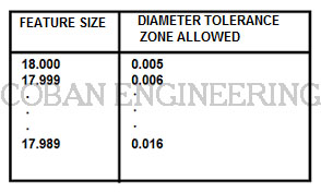
D-) The Maximum diameter of the shaft with perfect form shown in a gauge with diameter of 18.005 inch hole.
E-) The gauge will accept maximum diameter of the 18.005 inch shaft.
F-) The Minimum shaft diameter of the 17.989 inch, the gauge will accept the 0.016 variation in straightness of the diameter.
Copyright ©2010-2023 Coban Engineering.All Rights Reserved.


