- GD&T
GENERAL DIMENSIONING- International Paper Size Standards
- Technical Drawing Styles
- ISO And ANSI Projections
- ANSI Technical Drawing Views
- Technical Drawing Dimesioning Types
- ANSI and ISO Geometric Tolerancing Symbols
- Geometric Tolerancing Reading
- Taylor Principle Rule#1
- Form Tolerances
- Profile Tolerances
- Orientation Tolerances
- Location Tolerances
- Runout Tolerances
- TOLERANCES
ANSI AND ISO- Tolerancing and Engineering Standards
- Hole and Shaft Basis Limits And Fits
- ISO International System For Limits And Fits
- International Tolerance Grade (IT)
- Fundamental Deviations For Hole and Shaft Basis
- ISO Tolerance Band IT01-IT16
- Calculation Of International Tolerance
- Calculation of Upper and Lower Deviation For Shaft
- Calculation of Upper and Lower Deviation For Holes
- ISO Shaft Tolerances (3mm-400mm)
- ISO Shaft Tolerances (400mm-3150mm)
- ISO Hole Tolerances (3mm-400mm)
- ISO Hole Tolerances (400mm-3150mm)
- ANSI Standard Limits and Fits
- METAL CUTTING TECHNOLOGIES
- Terms and Definitions of the Cutting Tools
- Cutting Tool Materials
- Selection of Carbide to machine the work-part
- Identification System For Indexable Inserts
- Work-Part Materials
- Machinability and the specific cutting force
- Machinability of the Certain Material Evaluations
- Cutting Forces and Chip Formations
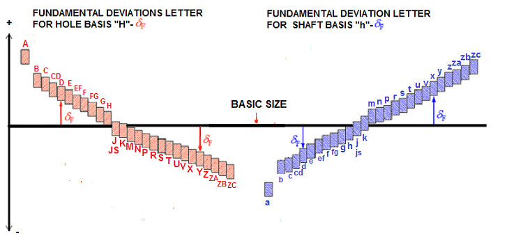
Fundamental Deviations Letter For Hole and Shaft Basis.
The Value for the Hole from "A" to "H" are positive (+), for the Shaft from "a" to "h" negative (-).
The Value of the Hole from "J" to "K" either positive (+) or negative (-), for Shaft form "j" to "k" either
positive (+) or negative (-).

Applications with ISO 286/ANSI B4.2-1978 International Tolerance Grade.
For best fit selection for a specific applications many factors can be effective. Such as speed, temperatures, length
engagement,
materials, lubrications, humidity, bearing load and etc. To satisfy extreme conditions the best
preferred fit must be considered. The
tolerances indicated by the International Tolerance (IT) Grades are general
guide to machining process given in ISO 286/ANSI B4.2-1978 showmen in the below
table.
| APPLICATIONS and PROCESS | IT Grade Range |
| LAPPING AND HONING | IT1, IT2, IT3, IT4, IT5, |
| CYLINDRICAL TURNING AND DIAMOND TURNING | IT4, IT5, IT6, IT7 |
| PLANE/ SURFACE GRINDING | IT5, IT6, IT7, IT8, IT9 |
| BROACHING AND REAMING | IT5, IT6, IT7, IT8, IT9 |
| BORING AND TURNING | IT6, IT7, IT8, IT9, IT10, IT11, IT12 |
| SAWING | IT9, IT10, IT11 |
| POWDER METAL-SINTERED | IT7, IT8, IT9,IT10 |
| MILLING | IT9,IT10,IT11, IT12, IT13 |
| PLANING, SHAPING, COLD ROLLING AND DRAWING | IT10, IT11, IT12, IT13,IT14, |
| COLD ROLLING AND DRAWING | IT 4, IT5, IT6,IT7 |
| DRIILING | IT11, IT12,IT13, IT14 |
| DIE CASTING | IT12,;IT13,IT14, IT15 |
| PUNCHING AND FORGING | IT13,IT14, IT15,IT16 |
| HOT ROLLING, FALME CUTTING AND SAND CASTING | IT1 4,IT15, IT16 |
ISO 286 TOLERANCE BAND IT01 To IT7
Tolerance Band Given Below (IT01 To IT7) In Micrometer=(10-3)mm
Example: IT1 For Nominal Size 0-3mm; 0.8μm=0.8x(10-3)=0.0008mm
| NOMINAL( BASIC) SIZES (mm) | INTERNATIONAL TOLERANCE GRADES | ||||||||||||||||||
| OVER | UP TO INCL. | IT01 | IT0 | IT1 | IT2 | IT3 | IT4 | IT5 | IT6 | IT7 | |||||||||
| 0 | 3 | 0.3 | 0.5 | 0.8 | 1.2 | 2 | 3 | 4 | 6 | 10 | |||||||||
| 3 | 6 | 0.4 | 0.6 | 1 | 1.5 | 2.5 | 4 | 5 | 8 | 12 | |||||||||
| 6 | 10 | 0.4 | 0.6 | 1 | 1.5 | 2.5 | 4 | 6 | 9 | 15 | |||||||||
| 10 | 18 | 0.5 | 0.8 | 1.2 | 2 | 3 | 5 | 8 | 11 | 18 | |||||||||
| 18 | 30 | 0.6 | 1 | 1.6 | 2.6 | 4 | 6 | 9 | 13 | 21 | |||||||||
| 30 | 50 | 0.8 | 1 | 1.6 | 2.6 | 4 | 7 | 11 | 16 | 25 | |||||||||
| 50 | 80 | 0.8 | 1.2 | 2 | 3 | 5 | 8 | 13 | 19 | 30 | |||||||||
| 80 | 120 | 1 | 1.5 | 2.5 | 4 | 6 | 10 | 16 | 22 | 35 | |||||||||
| 120 | 180 | 1.2 | 2 | 3,5 | 5 | 8 | 12 | 18 | 25 | 40 | |||||||||
| 180 | 250 | 2 | 3 | 4.5 | 7 | 10 | 14 | 20 | 29 | 46 | |||||||||
| 250 | 315 | 2.5 | 4 | 6 | 8 | 12 | 16 | 23 | 32 | 62 | |||||||||
| 315 | 400 | 3 | 5 | 7 | 9 | 13 | 18 | 25 | 36 | 57 | |||||||||
| 400 | 500 | 4 | 6 | 8 | 10 | 16 | 20 | 27 | 40 | 63 | |||||||||
| 500 | 630 | 4.5 | 6 | 9 | 11 | 16 | 22 | 30 | 44 | 70 | |||||||||
| 630 | 800 | 5 | 7 | 10 | 12 | 18 | 25 | 35 | 50 | 80 | |||||||||
| 800 | 1000 | 5.5 | 8 | 11 | 15 | 21 | 29 | 40 | 56 | 90 | |||||||||
| 1000 | 1250 | 6.5 | 9 | 13 | 18 | 24 | 34 | 46 | 66 | 105 | |||||||||
| 1250 | 1600 | 8 | 11 | 16 | 21 | 29 | 40 | 54 | 78 | 126 | |||||||||
| 1600 | 2000 | 9 | 13 | 18 | 26 | 35 | 48 | 65 | 92 | 160 | |||||||||
| 2000 | 2500 | 11 | 16 | 22 | 30 | 41 | 67 | 77 | 110 | 175 | |||||||||
| 2500 | 3150 | 13 | 18 | 26 | 36 | 60 | 69 | 93 | 135 | 210 | |||||||||
Equation Chart to Calculate Fundamental Deviation of Shaft Size Up to 500mm (Geometric Mean Dia "mm")
| FORMULAE FOR FUNDAMENTAL DEVIATION FOR SHAFTS SIZES UP TO 500 mm | |||
| UPPER DEVIATION (es) | LOWER DEVIATION (ei) | ||
| Shaft Designation | In Microns (for D in mm) | Shaft Designation | In microns (for D in mm) |
| a | = -(265 + 1.32D) for D ≤ 120 ;and = – 3.52D for D > 120 | j5 to j8 | No formula |
| js | ITx1/2 | ||
| k4 to k7 | =+ 0.6x 3
√ D |
||
| b | = – (140 + 0.852D); for D <160 ;And = – 1.82D for D > 160 |
||
| k for Grade ≤3 and ≥4 | =0 | ||
| m | = + (T7-IT6) | ||
| c | = – 52D0.2 for D ≤ 40 = -(95 + 0.82) for D> 40 |
||
| n | = + 5D0.34 | ||
| P | = + IT7 + 0 to 5 | ||
| cd | G.M. of values for c and d | r | = geometric mean of values for p and s |
| d | = – 16D0.44 | ||
| s | = IT8 + 1 to 4; for D ≤50 = + 7T7 to + 0.4D; for D > 50 |
||
| e | = -11D0.41 | ||
| ef | G.M. of values for e and f | ||
| f | = -5.5D0.41 | t | = + IT7 + 0.63D |
| fg | G.M. of values for f and g | u | = + IT7 + D |
| g | = -2.5D0.34 | V | = + IT1 + 1.2525D |
| h | = 0 | X | = + IT7 + 1.62D |
| y | = + IT7 + 2D | ||
| z | = + IT7 + 2.52D | ||
| za | = IT8 + 3 + 3.152D | ||
| zb | = + IT9 + 4D | ||
| zc | = + IT10 + 4D | ||
| ALL DEVIATIONS EXCEPT THOSE GIVEN BELOW | GENERAL RULE: Hole limits are identical with the shaft limits of the same symbole (Letter and Grade)but disposed on the other side of the zero line.EI=-es (EI is equal upper deviation of shaft of the same letter symbol but of opposite sign.) |
||||
| N | IT9 and Closer Grades | ES=0 | |||
| For Size Above 3mm | J,K.M, and N | Up to Grade IT8 Inclusive |
SPECIALS RULES: ES= Lower deviation ei of the shaft of the same letter symbol but one grade finer and of opposite sign increased by the difference between the tolerances of the two grades in; ei+ITx=ES+ITn and ei-ITn= ES-ITx (x=n-1) |
||
| For Size Above 3mm | P to ZC | Up to Grades 7 inclusive | |||
Copyright ©2010-2023 Coban Engineering.All Rights Reserved.


