- GD&T
GENERAL DIMENSIONING- International Paper Size Standards
- Technical Drawing Styles
- ISO And ANSI Projections
- ANSI Technical Drawing Views
- Technical Drawing Dimesioning Types
- ANSI and ISO Geometric Tolerancing Symbols
- Geometric Tolerancing Reading
- Taylor Principle Rule#1
- Form Tolerances
- Profile Tolerances
- Orientation Tolerances
- Location Tolerances
- Runout Tolerances
- TOLERANCES
ANSI AND ISO- Tolerancing and Engineering Standards
- Hole and Shaft Basis Limits And Fits
- ISO International System For Limits And Fits
- International Tolerance Grade (IT)
- Fundamental Deviations For Hole and Shaft Basis
- ISO Tolerance Band IT01-IT16
- Calculation Of International Tolerance
- Calculation of Upper and Lower Deviation For Shaft
- Calculation of Upper and Lower Deviation For Holes
- ISO Shaft Tolerances (3mm-400mm)
- ISO Shaft Tolerances (400mm-3150mm)
- ISO Hole Tolerances (3mm-400mm)
- ISO Hole Tolerances (400mm-3150mm)
- ANSI Standard Limits and Fits
- METAL CUTTING TECHNOLOGIES
- Terms and Definitions of the Cutting Tools
- Cutting Tool Materials
- Selection of Carbide to machine the work-part
- Identification System For Indexable Inserts
- Work-Part Materials
- Machinability and the specific cutting force
- Machinability of the Certain Material Evaluations
- Cutting Forces and Chip Formations
ISO Tolerance Systems For Limits And Fits
This standard can be described as ISO 286:1988.This standard is being described in USA as ANSI (ANSI B4.2-1978). American National Standard (ANSI B4.2-1978) describes ISO standard of metric fits and limits for mating machine parts as approved for general engineering usage. This Standard is used as an international standard for linear dimension tolerances. This ISO system is identical with the European standard (EN 20286:1993) and defines an internationally recognized system of tolerances, deviations and fits. This system has been accepted in most industrially developed countries in identical or by modifying wording system as a their national standard like Japan, British, USA (JIS B 0401, DIN ISO 286, BS EN 20286, CSN EN 20286, etc.). General terms of shaft and hole can also be taken to refer to the space contained by two parallel faces of any part, e.g. fits of keys in grooves.
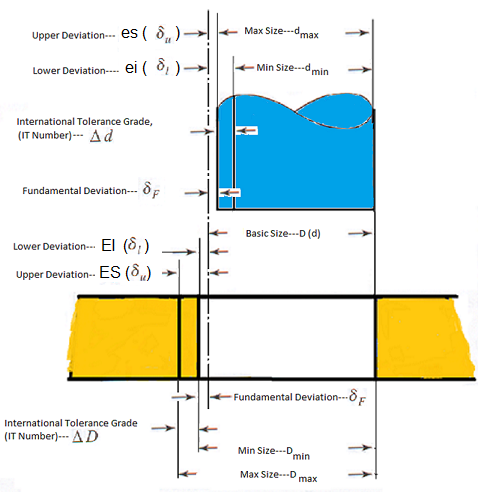
The most important term relating to fits and limits are showmen in the figure below;

Deviations from the exact dimensions are unavoidable due to the nature of manufacturing processes.
Deviation: Difference between the size and the corresponding basic
size. The basic size is assigned as limits of deviation.
it is same for both parts of their fits.
Lower Deviation: Difference between the min limit of part's size and corresponding basic size. It is designated "EI" for Hole, "ei" for shaft
Upper Deviation: Difference between the max limit of part's size and the corresponding basic size.
It is designated "ES" for hole," es" for shaft
Fundamental Deviation: One of the deviations closest to the basic size.
For easy understanding of the "es", "ei", "ES", and "EI" and identification of their negative and positive values, the letter may be interpreted as follow;
es: Error from zero line (Basic Size) to superior size of shaft.
ei: Error from zero line (Basic Size) to inferior size of shaft.
ES: Error from zero line (Basic Size) to superior size of hole.
EI: Error from zero line (Basic Size) to inferior size of hole.
Tolerance Zone: A zone representing the tolerance and its position in relating to the
basis size.
The tolerance zone is also defined as a spherical zone limited by the upper and lower limit dimensions of the part.
Tolerance: The algebraic difference between the max and min limits on the part.
International Tolerance Grade (IT)
IT grade is a group of tolerances. Each of the tolerances of this system is marked "IT" with attached grade of accuracy (IT01, IT0, IT1 ... IT18).IT Grades reference ISO 286. The magnitude of the tolerance zone is the variation in part size. IT groups of tolerances such that tolerances for a particular IT number have the same relative level of accuracy but vary depending on the basic size. A smaller grate of IT number provides a smaller tolerance zone. The fundamental IT deviation for hole basis is designated by "H", the shaft designated by "h".
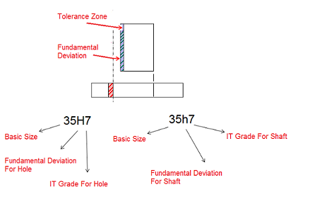
Tolerance Symboles:The tolerance symbol is established by combining the IT grade number and position letter for tolerance.
Capital letter like "H" for hole, and lower case letter like "h" for shaft.
Showing Internal part with IT symbol:

Showing External Part with IT symbol:

Application Field of International Tolerances of ISO 286 system:

| APPLICATIONS | IT Grade Range |
| Measuring Instruments and Production of Gauges | IT01, IT0, IT1, IT2, IT3, IT4, IT5, IT6 |
| General Engineering/Industry and Precision Fit | IT 5, IT6, IT7, IT8, IT9, IT10, IT11, IT12 |
| Semi Finished Product | IT11, IT14, IT15, IT16 |
| Structural Engineering | IT16, IT17, IT18 |
Copyright ©2010-2023 Coban Engineering.All Rights Reserved.


