- GD&T
GENERAL DIMENSIONING- International Paper Size Standards
- Technical Drawing Styles
- ISO And ANSI Projections
- ANSI Technical Drawing Views
- Technical Drawing Dimesioning Types
- ANSI and ISO Geometric Tolerancing Symbols
- Geometric Tolerancing Reading
- Taylor Principle Rule#1
- Form Tolerances
- Profile Tolerances
- Orientation Tolerances
- Location Tolerances
- Runout Tolerances
- TOLERANCES
ANSI AND ISO- Tolerancing and Engineering Standards
- Hole and Shaft Basis Limits And Fits
- ISO International System For Limits And Fits
- International Tolerance Grade (IT)
- Fundamental Deviations For Hole and Shaft Basis
- ISO Tolerance Band IT01-IT16
- Calculation Of International Tolerance
- Calculation of Upper and Lower Deviation For Shaft
- Calculation of Upper and Lower Deviation For Holes
- ISO Shaft Tolerances (3mm-400mm)
- ISO Shaft Tolerances (400mm-3150mm)
- ISO Hole Tolerances (3mm-400mm)
- ISO Hole Tolerances (400mm-3150mm)
- ANSI Standard Limits and Fits
- METAL CUTTING TECHNOLOGIES
- Terms and Definitions of the Cutting Tools
- Cutting Tool Materials
- Selection of Carbide to machine the work-part
- Identification System For Indexable Inserts
- Work-Part Materials
- Machinability and the specific cutting force
- Machinability of the Certain Material Evaluations
- Cutting Forces and Chip Formations
JIS Standard Paper Sizes: JIS (Japanese Industrial Standard ) defines two series of paper sizes: the JIS A-series and the JIS B-series. the JIS A-series is identical to the ISO216 standard A-series, only with slightly different tolerances. However, the JIS B-series is completely different to the ISO216 standard B-series. the area of Japanese B-series paper is 1.5 times that of the corresponding A-series paper, so the lenghd ratio is approximately 1.22 times the lenghd of the corresponding A-series paper. the aspect ratio remains the same for JIS B-series paper as it is for A-series paper. Both JIS A and B-series paper is widely used throughout Japan and Taiwan.
| Format | JIS B series | Shiroku ban | Kiku | |||
| Size | Metric (mm) | Inch (in) | Metric (mm) | Inch (in) | Metric (mm) | Inch (in) |
| 0 | 1030x1456 | 40.55x57.32 | ||||
| 1 | 728x1030 | 28.66x40.55 | ||||
| 2 | 515x728 | 20.28x28.66 | ||||
| 3 | 364x515 | 14.33x20.28 | ||||
| 4 | 257x364 | 10.12x14.33 | 264x379 | 10.39x14.92 | 227x306 | 8.94x12.05 |
| 5 | 182x257 | 7.17x10.12 | 189x262 | 7.44x10.31 | 151x227 | 5.94x8.94 |
| 6 | 128x182 | 5.04x7.17 | 127x188 | 5.00x7.40 | ||
| 7 | 91x128 | 3.58x5.04 | ||||
| 8 | 64x91 | 2.52x3.58 | ||||
| 9 | 45x64 | 1.77x2.52 | ||||
| 10 | 32x45 | 1.26x1.77 | ||||
| 11 | 22x32 | 0.87x1.26 | ||||
| 12 | 16x22 | 0.63x0.87 | ||||
Technical Drawing Style
There are some technical drawing styles to follow to make technical drawing either freehand or by using CAD applications. These are Isometric, Orthographic, Oblique, and Perspective.
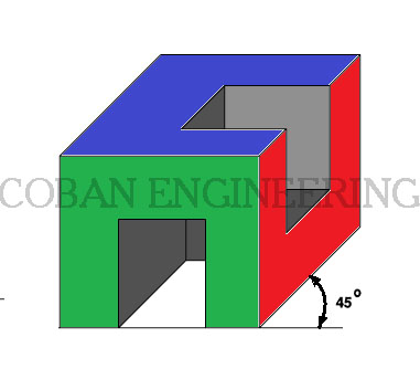
Oblique Drawing: Oblique Drawing/projection is a method of drawing objects in 3 dimensions. Oblique projections focus on the front of the object, but also show the top and one side, and are drawn at 45 Degree angle. As shown below;
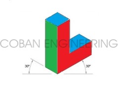
Isometric Drawing: Isometric drawing/projection is a method of visually representing three-dimensional objects in two dimensions in engineering technical drawings. Isometric is an easy method of drawing 3D image. All lines in isometric drawings are drawn to scale. In isometric drawing all the vertical lines are drawn vertically but all horizontal lines are drawn at 30 degrees to the base line. As shown below;
Orthographic Drawing: Orthographic drawing/projection is a means of representing a three-dimensional object in two dimensions. Orthographic projection show the top, sides, and the bottom of and object. Also orthographic projection is called multi view drawings. The views are always drawing to scale. Orthographic projection may have six views or three views. Three view drawn is most common.
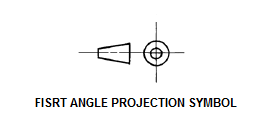
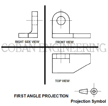
ISO and ANSI Projection Symbols used to define First Angle Projection and Third Angle Projection.
First-angle projection is the ISO standard and is primarily used in Europe. When the 3D object is projected into 2D "paper" After projected Front view, the top view is under the front view, the right view is at the left of the front view. The symbol for first angle projection shown as follow;


Copyright ©2010-2023 Coban Engineering.All Rights Reserved.