- GD&T
GENERAL DIMENSIONING- International Paper Size Standards
- Technical Drawing Styles
- ISO And ANSI Projections
- ANSI Technical Drawing Views
- Technical Drawing Dimesioning Types
- ANSI and ISO Geometric Tolerancing Symbols
- Geometric Tolerancing Reading
- Taylor Principle Rule#1
- Form Tolerances
- Profile Tolerances
- Orientation Tolerances
- Location Tolerances
- Runout Tolerances
- TOLERANCES
ANSI AND ISO- Tolerancing and Engineering Standards
- Hole and Shaft Basis Limits And Fits
- ISO International System For Limits And Fits
- International Tolerance Grade (IT)
- Fundamental Deviations For Hole and Shaft Basis
- ISO Tolerance Band IT01-IT16
- Calculation Of International Tolerance
- Calculation of Upper and Lower Deviation For Shaft
- Calculation of Upper and Lower Deviation For Holes
- ISO Shaft Tolerances (3mm-400mm)
- ISO Shaft Tolerances (400mm-3150mm)
- ISO Hole Tolerances (3mm-400mm)
- ISO Hole Tolerances (400mm-3150mm)
- ANSI Standard Limits and Fits
- METAL CUTTING TECHNOLOGIES
- Terms and Definitions of the Cutting Tools
- Cutting Tool Materials
- Selection of Carbide to machine the work-part
- Identification System For Indexable Inserts
- Work-Part Materials
- Machinability and the specific cutting force
- Machinability of the Certain Material Evaluations
- Cutting Forces and Chip Formations
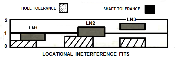
c-) Locational Interference Fits [LN]:These fits are used where accuracy of location is prime importance.Locational interference fits are used for parts requiring rigidity and alignment with no special requirements for bore pressure.The parts can be assembled or disassembled using cold pressing and greater forces or hot pressing. Such fits are not for parts designated to transmit frictional loads from one part to another by virtue of the tightness of fit. SHAFT "p6" with Hole "H7" gives a true interference fit. It is the standard press fit for steel , cast iron, or brass to steel assemblies. The amount of interference is too small for satisfactory press fit to be obtained in materials of low modulus of elasticity such as light alloys. For these, SHAFT "s6" with Hole "H7" is used and typical applications are collars pressed on to shafts, valves seatings, etc.
Graphical Representation of ANSI B4.1-1967 Locational Interference Fits Table
Locational Interference Limits and Fits For Cylindirical Parts
[(ANSI B4.1-1967,R1987)]
All limits shown in chart below are in thousandths of an inches. Symbols H7,p6, etc. are Shaft and Hole designations used in American-British-Canadian System (ABC). Limits for Shaft and Hole are applied algebraically to the Nominal (basic) size to obtain the limits of the size for the parts. All data given in bold in the chart below are in accordance with ABC agreements. The values given under the "Clearance Limits Column" represent min and max amounts of clearance resulting from application of standard tolerance limits.
| VALUES SHOWN BELOW ARE IN THOUSANDTHS OF AN INCHES | ||||||||||
| Nominal (Basic) Size Renges (Inches) |
Class LN1 | Class LN2 | Class LN3 | |||||||
| Interference Limits | Standard Tolerance Limits | Interference Limits |
Standard Tolerance Limits | Interference Limits | Standard Tolerance Limits |
|||||
| Over | To | Hole H6 | Shaft n5 | Hole H7 | Shaft p6 |
Hole H7 | Shaft r6 |
|||
| 0 | 0.12 | 0 0.45 | +0.25 0 | +0.45 +0.25 |
0 0.65 |
+0.4 0 | +0.65 +0.4 | 0.1 0.75 | +0.4 0 | +0.75 +0.5 |
| 0.12 | 0.24 | 0 0.5 | +0.3 0 | +0.5 +0.3 | 0 0.8 |
+0.5 0 | +0.8 +0.5 | 0.1 0.9 | +0.5 0 | +0.9 +0.6 |
| 0.24 | 0.40 | 0 0.65 | +0.4 0 | +0.65 +0.4 | 0 1.0 |
+0.6 0 | +1.0 +0.6 | 0.2 1.2 | +0.6 0 | +1.2 +0.8 |
| 0.40 | 0.71 | 0 0.8 | +0.4 0 | +0.8 +0.4 | 0 1.1 |
+0.7 0 | +1.1 +0.7 | 0.3 1.4 | +0.7 0 | +1.4 +1.0 |
| 0.71 | 1.19 | 0 1.0 | +0.5 0 | +1.0 +0.5 | 0 1.3 |
+0.8 0 | +1.3 +0.8 | 0.4 1.7 | +0.8 0 | +1.7 +1.2 |
| 1.19 | 1.97 | 0 1.1 | +0.6 0 | +1.1 +0.6 | 0 1.6 |
+1.0 0 | +1.6 +1.0 | 0.4 2.0 | +1.0 0 | +2.0 +1.4 |
| 1.97 | 3.15 | 0.1 1.3 | +0.7 0 | +1.3 +0.8 | 0.2 2.1 |
+1.2 0 | +2.1 +1.4 | 0.4 2.3 | +1.2 0 | +3.2 +1.6 |
| 3.15 | 4.73 | 0.1 1.6 | +0.9 0 | +1.6 +1.0 | 0.2 2.5 |
+1.4 0 | +2.5 +1.6 | 0.6 2.9 | +1.4 0 | +2.9 +2.0 |
| 4.73 | 7.09 | 0.2 1.9 | +1.0 0 | +1.9 +1.2 | 0.2 2.8 |
+1.6 0 | +2.8 +1.8 | 0.9 3.5 | +1.6 0 | +3.5 +2.5 |
| 7.09 | 9.85 | 0.2 2.2 | +1.2 0 | +2.2 +1.4 | 0.2 3.2 |
+1.8 0 | +3.2 +2.0 | 1.2 4.2 | +1.8 0 | +4.2 +3.0 |
| 9.85 | 12.41 | 0.2 2.3 | +1.2 0 | +2.3 +1.4 | 0.2 3.4 |
+2.0 0 | +3.4 +2.2 | 1.5 4.7 | +2.0 0 | +4.7 +3.5 |
| 12.41 | 15.75 | 0.2 2.6 | +1.4 0 | +2.6 +1.6 | 0.3 3.9 |
+2.2 0 | +3.9 +2.5 | 2.3 5.9 | +2.2 0 | +5.9 +4.5 |
| 15.75 | 19.69 | 0.2 2.8 | +1.6 0 | +2.8 +1.8 | 0.3 4.4 |
+2.5 0 | +4.4 +2.8 | 2.5 6.6 | +2.5 0 | +6.6 +5.0 |
| 19.69 | 30.09 | +2.0 0 | 0.5 5.5 | +3.0 0 | +5.5 +3.5 |
4.0 9.0 | +3.0 0 | +9.0 +7.0 |
||
| 30.09 | 41.49 | +2.5 0 | 0.5 7.0 | +4.0 0 | +7.0 +4.5 |
5.0 11.5 | +4.0 0 | +11.5 +9.0 |
||
| 41.49 | 56.19 | +3.0 0 | 1.0 9.0 | +5.0 0 | +9.0 +6.0 |
+7.0 +15.0 | +5.0 0 | +15.0 +12.0 |
||
| 56.19 | 76.39 | +4.0 0 | 1.0 11.0 | +6.0 0 | +11.0 +7.0 |
10.0 20.0 | +6.0 0 | +20.0 +16.0 |
||
| 76.39 | 100.9 | +5.0 0 | 1.0 14.0 | +8.0 0 | +14.0 +9.0 |
12.0 25.0 | +8.0 0 | +25.0 +20.0 |
||
| 100.9 | 131.9 | +6.0 0 | 2.0 18.0 | +10.0 0 | 18.0 12.0 |
15.0 31.0 | +10.0 0 | +31.0 +25.0 |
||
| 131.9 | 171.9 | +8.0 0 | 4.0 24.0 | +12.0 0 | +24.0 +16.0 |
18.0 38.0 | +12.0 0 | +38.0 +30.0 |
||
| 171.9 | 200 | +10.0 0 | 4.0 30.0 | +16.0 0 |
+30.0 +20.0 | 24.0 50.0 | +16.0 0 | +50.0 +40.0 |
||
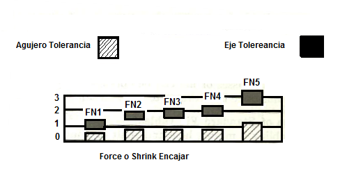
3-) Force or Shrink Fits [FN]:
These fits are designed, above all, for transfers of torsional moments using friction forces between Holes and Shafts. Force and Shrink Fits are a type of interference fit which seek to maintain constant hole pressure for all sizes. The interferece varies almost directly the diameter of the parts. The interference between the min and the max value is kept small to ensure that resulting pressure are reasonable. The value of interference/loading capacity of the fit increases with increasing class of the fit. When using force fit, surface unevenness of connected parts is partially stripped and smoothed. This results in reduction of the original assembly interference and thus reduction of the assembly loading capacity. The amount of mounting smoothness of the surface depends on load bearing treatment of the connected part edge surface, speed of press and mainly on the roughness of connected parts. The press speed should not exceed 2 mm/s. To prevent seizing, steel parts are usually greased. It is also necessary to grease contact areas in case of large couplings with large interference, where extremely high press forces are required. Parts from different materials may be dry-pressed. Greasing contact and coupling loading capacity. From the technological point of view, a force fit is relatively simple and undemanding; but, it shows lower assembly loading capacity and reliability than a transverse press/Shrink fit. Force and Shrink fits are described as follows;
FN1; Light Drive Fits: These type of fits are those requiring light assembly pressure, and they produce more or less permanent assemblies. They are suitable in cast-iron external members or for thin sections or long fits.
FN2; Medium Drive Fits: These type of fits are suitable for ordinary steel parts, or shrink fits on light sections. Medium Drive Fits are about the tightest fits that can be used with high-grade cast-iron external members.
FN3; Heavy Drive Fits: These type of fits are suitable for heavier steel parts or shrink fits in medium sections.
FN4;FN5 Force Drive Fits: These type of fits are for parts which can be highly and stressed or for shrink fits where the heavy pressing forces required are impractical.
Graphical Representation of ANSI B4.1-1967 Force and Shrink Fits
The allowance for forced fits is very important. The allowance for forced fit per inch diameter usually from 0.001 inch to 0.0025 inch. The fair average is being 0.0015 inch. The allowance per inch usually decreases as the diameter of the part increases. Thus the total allowance for a part diameter of 2 inches might be 0.004 inch. But for a part diameter of 8 inches the maximum allowance might not be over 0.009 or 0.0010 inches. The parts that need to be assembled by forced fit are generally made cylindrical. But sometimes they are slightly tapered. The advantages of the tapered surface are that the possibility of rubbing of the fitted surfaces are reduced. So less pressure will be required to assemble the parts. So that the parts are more easily separated when disassemble is required. Some lubricant should be applied to the surface of round part and the bore/hub before assembly. This lubricant can be lard oil mixed, etc. This will reduce the tendency of abrasion. The disadvantage of the taper fit is less reliable, because if the tapered part loosens , the entire fit is going to be free with little axial movement.


Copyright ©2010-2023 Coban Engineering.All Rights Reserved.