- GD&T
GENERAL DIMENSIONING- International Paper Size Standards
- Technical Drawing Styles
- ISO And ANSI Projections
- ANSI Technical Drawing Views
- Technical Drawing Dimesioning Types
- ANSI and ISO Geometric Tolerancing Symbols
- Geometric Tolerancing Reading
- Taylor Principle Rule#1
- Form Tolerances
- Profile Tolerances
- Orientation Tolerances
- Location Tolerances
- Runout Tolerances
- TOLERANCES
ANSI AND ISO- Tolerancing and Engineering Standards
- Hole and Shaft Basis Limits And Fits
- ISO International System For Limits And Fits
- International Tolerance Grade (IT)
- Fundamental Deviations For Hole and Shaft Basis
- ISO Tolerance Band IT01-IT16
- Calculation Of International Tolerance
- Calculation of Upper and Lower Deviation For Shaft
- Calculation of Upper and Lower Deviation For Holes
- ISO Shaft Tolerances (3mm-400mm)
- ISO Shaft Tolerances (400mm-3150mm)
- ISO Hole Tolerances (3mm-400mm)
- ISO Hole Tolerances (400mm-3150mm)
- ANSI Standard Limits and Fits
- METAL CUTTING TECHNOLOGIES
- Terms and Definitions of the Cutting Tools
- Cutting Tool Materials
- Selection of Carbide to machine the work-part
- Identification System For Indexable Inserts
- Work-Part Materials
- Machinability and the specific cutting force
- Machinability of the Certain Material Evaluations
- Cutting Forces and Chip Formations
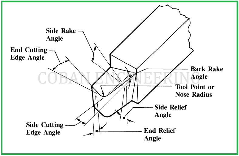
Back Rake: The back rake is the inclination of the face toward or away from the end or the end cutting edge of the tool. When the inclination is away from the end cutting edge, as shown in figure below. The back rake is positive. If the inclination is downward toward the end cutting edge the back rake is negative. See next figure below.
Side Rake: :The side rake is the inclination of the face toward or away from the side cutting edge. When the inclination is away from the side cutting edge, as shown in the figure below. The side rake is positive. If the inclination is toward the side cutting edge the side rake is negative. See following figure below.
The flank angles: The flank angles are defined in a way similar to the rake angles, though the line of intersection viewed here lies on the opposite side of the cutting edge plane Ps from the direction of feed motion, assumed, or actual as the case may be, then the flank angle is positive. Angles "αf", "αp", "αo" and "αn" are clearly defined in the corresponding planes, as shown in the figure above. The flank (clearance) angle is the angle between the tool cutting edge plane Ps and the intersection line formed by the tool-flank plane and the plane of measurement considered, as shown in the figure above.
The wedge angles: The wedge angles "βf", "βp", "βo" and "βn" are defined in the planes of measurements. It is the angle between the two intersection lines formed as the corresponding plane of measurement intersects with the rake and flank planes. For all the cases, the sum of rake, wedge and clearance angles is 90◦, i.e. See the formula in figure;
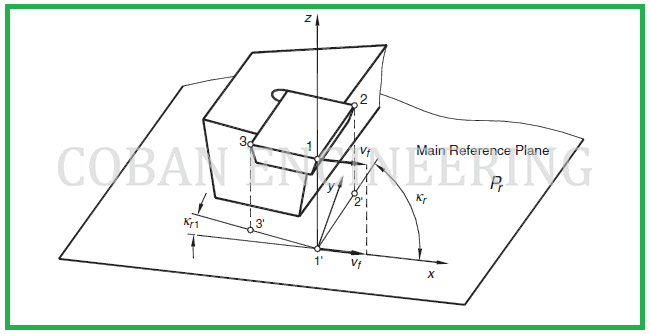
The orientation and inclination of the cutting edge: They are specified in the tool cutting edge plane "Ps". In this plane, the cutting edge inclination angle "λs" is the angle between the cutting edge and the reference plane. This angle is defined as always being acute and positive if the cutting edge, when viewed in a direction away from the selected point at the tool corner being considered, lies on the opposite side of the reference plane from the direction of primary motion. This angle can be defined at any point of the cutting edge. The sign of the inclination angle is well defined in the following figure of too langles-in-hand system.
The definition of the tool cutting edge angle: Tool cutting edge angle κr is shown in the figure below. It is defined as the acute angle that the tool cutting edge plane makes with the working plane assumed and is measured in the reference plane "Pr" . It can also be defined as the acute angle between the projection of the main cutting edge into the reference plane and the x direction. Angle "κr" is always positive and it is measured in a counter-clockwise direction from the position of the working plane assumed.


Copyright ©2010-2023 Coban Engineering.All Rights Reserved.