- GD&T
GENERAL DIMENSIONING- International Paper Size Standards
- Technical Drawing Styles
- ISO And ANSI Projections
- ANSI Technical Drawing Views
- Technical Drawing Dimesioning Types
- ANSI and ISO Geometric Tolerancing Symbols
- Geometric Tolerancing Reading
- Taylor Principle Rule#1
- Form Tolerances
- Profile Tolerances
- Orientation Tolerances
- Location Tolerances
- Runout Tolerances
- TOLERANCES
ANSI AND ISO- Tolerancing and Engineering Standards
- Hole and Shaft Basis Limits And Fits
- ISO International System For Limits And Fits
- International Tolerance Grade (IT)
- Fundamental Deviations For Hole and Shaft Basis
- ISO Tolerance Band IT01-IT16
- Calculation Of International Tolerance
- Calculation of Upper and Lower Deviation For Shaft
- Calculation of Upper and Lower Deviation For Holes
- ISO Shaft Tolerances (3mm-400mm)
- ISO Shaft Tolerances (400mm-3150mm)
- ISO Hole Tolerances (3mm-400mm)
- ISO Hole Tolerances (400mm-3150mm)
- ANSI Standard Limits and Fits
- METAL CUTTING TECHNOLOGIES
- Terms and Definitions of the Cutting Tools
- Cutting Tool Materials
- Selection of Carbide to machine the work-part
- Identification System For Indexable Inserts
- Work-Part Materials
- Machinability and the specific cutting force
- Machinability of the Certain Material Evaluations
- Cutting Forces and Chip Formations
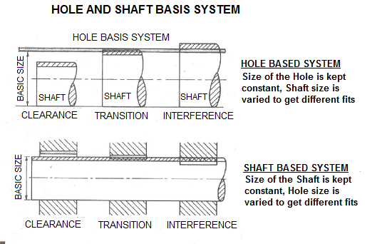
Hole And Shaft Basis Limits And Fits
Hole basis limits and fits with Shaft basis limits and fits have been given as an example in the chart below. The definitions for descriptions given in the chart explained as follows. The chart below gives simple understanding of Hole Basis Limits and Shaft Basis Limits. Some of the application and some of the selected Preferred Fits for Hole and Shaft Basis system have been given followed by Fits explanations.
| More Clearance (Close to Top of The Chart) More Interference (Close to Bottom of The Chart) | Clearance Fits | Description | Hole Basis | Shaft Basis |
| Free Running | H9/d9 | D9/h9 | ||
| Loose Running | H11/c11 | C11/h11 | ||
| Easy Running | H8/f8 | F8/h8 | ||
| Sliding | H7/g6 | G7/h6 | ||
| Close Clearance | H8/f7 | F8/h7 | ||
| Locational Clearance | H7/h6 | H6/h7 | ||
| Transition Fits | Location- slight interference | H7/k6 | K7/h7 | |
| Location/Transition | H7/n6 | N7/h6 | ||
| Interference Fits | Location/Interference | H7/p6 | P7/h6 | |
| Medium Drive Fit | H7/s6 | S7/h6 | ||
| Force Fit | H7/u6 | U7/h6 |
Free Running; This type of tolerance can be usable where any special
requirements for accuracy in not essential, but good for wide temperature
variation, heavy journal pressures and high running speeds.
Some of the applications: Multiple fits of shafts of production and piston machines, parts rotating
very rarely or only swinging..
Some of the selected Preferred fits: H9/d9, D9/h9, H9/C9, H9/d10, D9/h8, H8/d9, H8/d8, D10/h9,
Loose Running; Fits For wide commercial tolerances/clearances or
allowances with parts on external members.
Some of the applications: Fits of parts exposed to corrosive
effects, pivots, latches, contamination
with dust and thermal or mechanical deformations.
Some of the selected
Preferred fits:
H11/c11, H11/a11, C11/h11, H11/c9, D11/h11, H11/d11, A11/h11,
Easy Running; This is tuning fits with smaller clearances with
general requirements for fit accuracy.
Some of the applications: Main fits of machine tools. General fits of shafts, regulator bearings,
machine tool spindles, sliding rods.
Some of the selected Preferred fits: H8/f8, H9/f8, F8/h6, F8/h7, H8/f7, H7/f7,
Sliding/Running Fit; This fit does not provide freely running. This
running/sliding tolerance fits with very small clearances for accurate guiding of
shafts. This kind of tolerance helps the parts to move and turn freely and
locate accurately.
Some of the applications: sliding gears and clutch disks, parts of machine tools, pistons of hydraulic machines, rods sliding in bearings,
grinding machine spindles, crankshaft journals.
Some of the selected
Preferred fits: H7/g6, H8/g7, G7/h6,
Close Clearance ( Spigots and Locations);This fit is for accurate
location at moderate speeds and journal pressures, and running on accurate
machine parts. Running fits with smaller clearances with general requirements for fit accuracy.
Some of the applications: General fits of shafts, machine tool spindles, main
fits of machine tools, regulator bearings, sliding rods.
Some of the selected
Preferred fits: H8/f7, F8/h7, F8/h6, H9/f8, H8/f8, H7/f7,
Locational Clearance; For locating stationary parts, it provides snug
fit. It provides freely assemble and disassemble. This
fit helps for precise guiding and centering of parts and mounting by sliding on
without use of any great force, after lubrication the parts can be turned and
slid by hand.
Some of the applications: Roller guides. precise guiding of machines and preparations,
exchangeable wheels.
Some of the selected Preferred fits: H7/h6, H8/h7, H8/h9, H8/h8,
Location- slight interference; This type of fit compromise between interference and
clearance for accurate location. With
this fit, the parts can be assemble or disassemble without great force using a
rubber mallet.
Some of the applications: Clutches, demountable fits of hubs of gears and pulleys, manual
wheels, brake disks.
Some of the selected Preferred fits: H7/k6, H8/k7, K7/h6, K8/h7,
Location/Transition; This fit for accurate location where greater
interference permissible. It is fixed fits with small interferences or negligible
clearances. Mounting of fits using pressing and light force.
Some of the applications: Armatures of electric motors on shafts, gear rims, fixed plugs,
driven bushings, flushed bolts.
Some of the selected Preferred fits: H7/n6, H8/n7, H8/p7, H7/m6, H8/m7, M8/h6, N7/h6, N8/h7,
Location/Interference; This type of fit where the assembled parts
requiring rigidity and great alignment with prime accuracy of location. Press
fit which can be separated, pressed fits with guaranteed interference. Assembly
of the parts can be carried out using cold pressing.
Some of the applications: Bearing bushings, Hubs of clutch disks.
Some of the selected
Preferred fits: H7/p6, H7/r6, H8/r7, P7/h6, R7/h6,
Medium Drive Fit This fit for shrink fit on light section or
ordinary steel parts. Pressed fits with medium interference, assembly of parts
using hot pressing, assembly using cold pressing only with use of large forces.
the tightest tolerance usable for cast iron.
Some of the applications: Permanent coupling of gears with shafts, bearing bushings.
Some of the selected
Preferred fits: H7/s6, H8/s7, H7/t6, H8/t7, S7/h6, T7/h6,
Force Fit; This fit suitable for parts which can be highly
stressed. Pressed fits with big interferences, assembly using pressing and great
forces under different temperatures of the parts. This fit for shrink fits where
the heavy pressing forces required are impractical.
Some of the applications: Permanent couplings of gears with shafts, flanges.
Some of the selected
Preferred fits: H7/u6, H8/u7, H8/u8, H8/x8, U7/h6, U8/h7,
Copyright ©2010-2023 Coban Engineering.All Rights Reserved.

