- GD&T
GENERAL DIMENSIONING- International Paper Size Standards
- Technical Drawing Styles
- ISO And ANSI Projections
- ANSI Technical Drawing Views
- Technical Drawing Dimesioning Types
- ANSI and ISO Geometric Tolerancing Symbols
- Geometric Tolerancing Reading
- Taylor Principle Rule#1
- Form Tolerances
- Profile Tolerances
- Orientation Tolerances
- Location Tolerances
- Runout Tolerances
- TOLERANCES
ANSI AND ISO- Tolerancing and Engineering Standards
- Hole and Shaft Basis Limits And Fits
- ISO International System For Limits And Fits
- International Tolerance Grade (IT)
- Fundamental Deviations For Hole and Shaft Basis
- ISO Tolerance Band IT01-IT16
- Calculation Of International Tolerance
- Calculation of Upper and Lower Deviation For Shaft
- Calculation of Upper and Lower Deviation For Holes
- ISO Shaft Tolerances (3mm-400mm)
- ISO Shaft Tolerances (400mm-3150mm)
- ISO Hole Tolerances (3mm-400mm)
- ISO Hole Tolerances (400mm-3150mm)
- ANSI Standard Limits and Fits
- METAL CUTTING TECHNOLOGIES
- Terms and Definitions of the Cutting Tools
- Cutting Tool Materials
- Selection of Carbide to machine the work-part
- Identification System For Indexable Inserts
- Work-Part Materials
- Machinability and the specific cutting force
- Machinability of the Certain Material Evaluations
- Cutting Forces and Chip Formations
6) Insert Thickness: The thickness is designated by a one- or two-digit number, which indicates the number of sixteenths of an inch in the thickness of the insert. It is a one-digit number when the number of sixteenths is a whole number; it is a two-digit number carried to one decimal place when the number of sixteenths of an inch is not a whole number.
7) Insert Cutting Point Configuration: The cutting point, or nose radius, is designated by a number representing 1⁄64 ths of an inch; a flat at the cutting point or nose, is designated by a letter: 0 for sharp corner; 1, 1⁄64 inch radius; 2, 1⁄32 inch radius; 3, 3⁄64inch radius; 4, 1⁄16 inch radius; 5, 5⁄64 inch radius; 6, 3⁄32 inch radius; 7, 7⁄64 inch radius; 8, 1⁄8 inch radius; A, square insert with 45° chamfer; D, square insert with 30° chamfer; E, square insert with 15° chamfer; F, square insert with 3° chamfer; K, square insert with 30° double chamfer; L, square insert with 15° double chamfer; M, square insert with 3° double chamfer; N, truncated triangle insert; and P, flatted corner triangle insert.
8) Insert Special Cutting Point Definition: The eighth position, if it follows a letter in the 7th position, is a number indicating the number of 1⁄64 ths of an inch measured parallel to the edge of the facet.
9) Insert Hand: R, right; L, left; to be used when required in ninth position.
10) Other Conditions for Insert: The tenth position defines special conditions (such as edge treatment, surface finish) as follows: A, honed, 0.0005 inch to less than 0.003 inch; B, honed, 0.003 inch to less than 0.005 inch; C, honed, 0.005 inch to less than 0.007 inch; J, polished, 4 micro-inch arithmetic average (AA) on rake surfaces only; T, chamfered, manufacturer's standard negative land, rake face only.
Indexable Insert Tool Holders
Indexable insert tool holders are made from a good grade of steel which is heat treated to a hardness of 44 to 48 Rc for most normal applications. Accurate pockets that serve to locate the insert in position and to provide surfaces against which the insert can be clamped are machined in the ends of tool holders. A cemented carbide seat usually is provided, and is held in the bottom of the pocket by a screw or by the clamping pin, if one is used. The seat is necessary to provide a flat bearing surface upon which the insert can rest and, in so doing, it adds materially to the ability of the insert to withstand the cutting load. The seating surface of the holder may provide a positive-, negative-, or a neutral-rake orientation to the insert when it is in position on the holder. Holders, therefore, are classified as positive, negative, or neutral rake.
Four basic methods are used to clamp the insert on the holder:
1) Clamping, usually top clamping;
2) Pin-lock clamping;
3) Multiple clamping using a clamp, usually a top clamp, and a pin lock;
4) Clamping the insert with a machine screw.
All top clamps are actuated by a screw that forces the clamp directly against the insert. When required,
a cemented-carbide, plate-type chip-breaker is placed between the clamp and the insert. Pin-lock clamps
require an insert having a hole: the pin acts against the walls of the hole to clamp the insert firmly
against the seating surfaces of the holder. Multiple or combination clamping, simultaneously using both
a pin-lock and a top clamp, is recommended when taking heavier or interrupted cuts. Holders are available
on which all the above-mentioned methods of clamping may be used. Other holders are made with only atop
clamp or a pin lock. Screw-on type holders use a machine screw to hold the insert in the pocket. Most standard
indexable insert holders are either straight-shank or offset-shank, although special holders are made having
a wide variety of configurations. styles are available in every shank size. Positive and negative rake tools
are also not available in every style or shank size. Some manufacturers provide additional shank sizes for
certain tool holder styles. For more complete details the manufacturers' catalogs must be consulted.
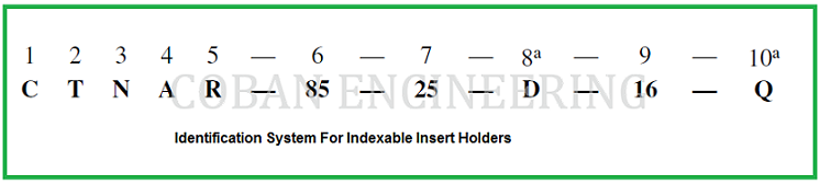
IDENTIFICATION SYSTEM FOR INDEXABLE INSERT HOLDERS
The following identification system conforms to the American National Standard, ANSI B212.5-2002, Metric Holders for Indexable Inserts. Each position in the system designates a feature of the holder in the following sequence:
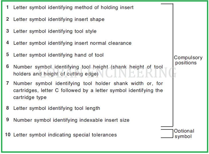
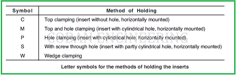
1) Method of Holding Horizontally Mounted Insert: The method of holding or clamping is designated by a letter: C, top clamping, insert without hole; M, top and hole clamping, insert with hole; P, hole clamping, insert with hole; S, screw clamping through hole, insert with hole; W, wedge clamping. ANSI B212.5-2002


Copyright ©2010-2023 Coban Engineering.All Rights Reserved.