- GD&T
GENERAL DIMENSIONING- International Paper Size Standards
- Technical Drawing Styles
- ISO And ANSI Projections
- ANSI Technical Drawing Views
- Technical Drawing Dimesioning Types
- ANSI and ISO Geometric Tolerancing Symbols
- Geometric Tolerancing Reading
- Taylor Principle Rule#1
- Form Tolerances
- Profile Tolerances
- Orientation Tolerances
- Location Tolerances
- Runout Tolerances
- TOLERANCES
ANSI AND ISO- Tolerancing and Engineering Standards
- Hole and Shaft Basis Limits And Fits
- ISO International System For Limits And Fits
- International Tolerance Grade (IT)
- Fundamental Deviations For Hole and Shaft Basis
- ISO Tolerance Band IT01-IT16
- Calculation Of International Tolerance
- Calculation of Upper and Lower Deviation For Shaft
- Calculation of Upper and Lower Deviation For Holes
- ISO Shaft Tolerances (3mm-400mm)
- ISO Shaft Tolerances (400mm-3150mm)
- ISO Hole Tolerances (3mm-400mm)
- ISO Hole Tolerances (400mm-3150mm)
- ANSI Standard Limits and Fits
- METAL CUTTING TECHNOLOGIES
- Terms and Definitions of the Cutting Tools
- Cutting Tool Materials
- Selection of Carbide to machine the work-part
- Identification System For Indexable Inserts
- Work-Part Materials
- Machinability and the specific cutting force
- Machinability of the Certain Material Evaluations
- Cutting Forces and Chip Formations
Forces in Metal Cutting: Equations can be derived to relate the forces that cannot be measured to the forces that can be measured:
F = Fc x sin α + Ft x cos α
N = Fc x cos α - Ft x sin α
Fs = Fc x cos ф - Ft x sinф
Fn = Fc x sinф + Ft x cosф
Based on these calculated force, shear stress and coefficient of friction can be determined.
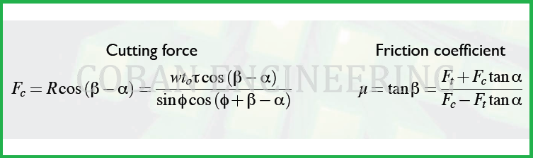
"F" (frictional force ) and "Fn" (Force normal to the Shear force; the resistance offered by the work-piece) can be used to define the coefficient of friction between the cutting tool and the chip. The friction force and its normal force can be added vectorially to form a resultant force, R. R is oriented at an angle, called the friction angle. The coefficient of friction and friction angle can be related and calculated as follows:

For the forces acting on the chip to be in balance, the resultant forces, R, must be colinear, opposite in direction and equal in magnitude. If cutting force and thrust force are known, these four equations can be used to calculate estimates of shear force, friction force, and normal force to friction. Based on these force estimates (F, N, Fs ),
can be determined.
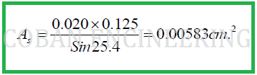
Example: Suppose that cutting force and thrust force are measured during an orthogonal cutting operation with values Fc = 350 N and Ft =285 N. The width of the orthogonal cutting operation w = 0.125 cm, to = 0.020cm, ф=25.4° , α= 10°

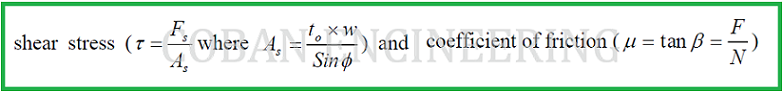
The shear plane area is calculated as:
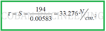
Thus, the sear stress, which equals the shear strength of the work material, is
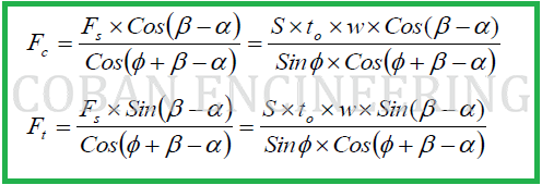
If the shear strength (S) of the work material is known, cutting force (Fc) and thrust force (Ft)
in an orthogonal cutting operation can be estimated:
Known:

Calculate the cutting force and the thrust force:


Copyright ©2010-2023 Coban Engineering.All Rights Reserved.